Getting more information about a USB device with rust and rusb (libusb)

In case you missed my previous posts I’m trying to reverse engineer how the Apple USB display service utility sends configuration commands to Apple Studio Display CRT monitors over USB.

I haven’t managed to run the original Apple software on QEMU successfully, but in the meantime I though I could use libusb to get a bit more information about the Apple Studio Display.
libusb is a C library and I’d rather not have to write C code. Luckily for me there is a rust wrapper for libusb called rusb.

Did I mention I’m hopping I’ll be able to use libusb and rust to create an open source command line tool that can change service settings on the Apple Studio Display?

Rust’s documentation is outstanding: I took me less time than I anticipated to go through enough chapters to feel confident to run one of rusb’s list device example and understand what was going on (disclaimer: I’m fluent in C#).

Below is the relevant output of the list device example I got while my computer was connected to the Apple Studio Display via USB.

Last login: Mon Mar 16 15:56:51 on ttys000
~
▶ cargo run
Finished dev [unoptimized + debuginfo] target(s) in 0.04s
Running `target/debug/open-usb-dsu`

Bus 020 Device 002 ID 05ac:9210   12 Mbps
Device Descriptor:
  bcdUSB              1.00
  bDeviceClass        0x00
  bDeviceSubClass     0x00
  bDeviceProtocol     0x00
  bMaxPacketSize0        8
  idVendor          0x05ac
  idProduct         0x9210
  bcdDevice          18.156
  iManufacturer          0 
  iProduct               1 
  iSerialNumber          0 
  bNumConfigurations     1
  Config Descriptor:
    bNumInterfaces         1
    bConfigurationValue    1
    iConfiguration         0 
    bmAttributes:
      Self Powered      true
      Remote Wakeup    false
    bMaxPower              0mW
    no extra data
    Interface Descriptor:
      bInterfaceNumber       0
      bAlternateSetting      0
      bNumEndpoints          1
      bInterfaceClass     0x03
      bInterfaceSubClass  0x00
      bInterfaceProtocol  0x00
      iInterface             0 
    [9, 33, 0, 1, 0, 1, 34, 1, 1]
      Endpoint Descriptor:
        bEndpointAddress    0x81 EP 1 In
        bmAttributes:
          Transfer Type          Interrupt
          Synch Type             NoSync
          Usage Type             Data
        wMaxPacketSize    0x0008
        bInterval            255

Bus 020 Device 001 ID 05ac:9110   12 Mbps
Device Descriptor:
  bcdUSB              1.00
  bDeviceClass        0x09
  bDeviceSubClass     0x00
  bDeviceProtocol     0x00
  bMaxPacketSize0        8
  idVendor          0x05ac
  idProduct         0x9110
  bcdDevice           0.01
  iManufacturer          0 
  iProduct               0 
  iSerialNumber          0 
  bNumConfigurations     1
  Config Descriptor:
    bNumInterfaces         1
    bConfigurationValue    1
    iConfiguration         0 
    bmAttributes:
      Self Powered      true
      Remote Wakeup    false
    bMaxPower              2mW
    no extra data
    Interface Descriptor:
      bInterfaceNumber       0
      bAlternateSetting      0
      bNumEndpoints          1
      bInterfaceClass     0x09
      bInterfaceSubClass  0x01
      bInterfaceProtocol  0x00
      iInterface             0 
    no extra data
      Endpoint Descriptor:
        bEndpointAddress    0x81 EP 1 In
        bmAttributes:
          Transfer Type          Interrupt
          Synch Type             NoSync
          Usage Type             Data
        wMaxPacketSize    0x0001
        bInterval            255

▶

The second device listed has a class of 0x09 which means it is the USB hub built in the display…
The first device however has a device class of 0x00 and interface class of 0x03. This seem to indicate it is a HID device (i.e. it’s telling its host “I’m a keyboard”).
Could it be that the color sync button on the display, acts as a keyboard and sends a special key combination that, when running mac os 9 launches the color sync software?

I’ll update this post with my findings soon.

Running Apple USB Display Service Utility via emulation (updated)

After turning on the Apple Studio Display and connecting it to a VGA output I was pleasantly surprised: I’d forgot how nice high resolution CRT monitors are. The main advantage of a CRT over an LCD display is the CRT will scale different resolution very nicely. On an LCD on the other hand, any resolution which is not the native one looks awful.
On the other side there is that flickering that LCD screens do not suffer from at all. But refresh rates 75 Hz or over, the effect is more than bearable.

The controls of the display are simple: brightness and contrast. The image looks the nicest with those controls set quite high.

I was able to set the maximum official resolution of 1600×1200 pixels @ 85 hertz. Annoyingly, at 85 Hz, the image isn’t perfectly centred: some the left of the image is cropped.
I have yet to experiment with custom resolution profiles to see if I can get higher refesh rates…

The display’s service manual mentions a tool named Apple USB Display Service Utility. It requires mac os 8.6 or 9 to run so I looked into emulating mac os 9 using QEMU. Unlike other power PC emulator, QEMU has support for external USB devices via libusb; you must either compile QEMU yourself or find a precompiled version that was compiled with libsub.

The original tool and all the service manual for all the apple displays studios are all on a disk image on macintosh garden. This resource is a gold mine. You’ll need stuff it expander to extract the .sit archive. Then you’ll end up with a .toast CD image. If you try to mount in on macos X it will not work, however, if you mount it to mac os 9, the image will mount on your desktop.

QEMU isn’t very user friendly. In order to connect a USB device to a virtual machine you first need to find out the vendor ID and device ID of the USB device. You can do this by searching in the tree of USB devices listed in macos X’s System Report.
I have stared a wiki page to list all the Vendor and Device IDs for Apple Studio Displays.

Then you can add -device USB to you qemu.command file:

#!/bin/bash
cd “$(dirname “$0″)”

./qemu-system-ppc -L pc-bios -boot c -M mac99,via=pmu -m 512 \
-prom-env ‘auto-boot?=true’ -prom-env ‘boot-args=-v’ -prom-env ‘vga-ndrv?=true’ \
-drive file=Service_Source.toast,format=raw,media=cdrom \
-drive file=MacOS9.2.img,format=raw,media=disk \
-netdev user,id=network01,hostfwd=tcp::5555-:548 -device sungem,netdev=network01 \
-device VGA,edid=on \

To tell QEMU to connect the Studio Display via USB to the virtual machine, add the following line to qemu.command before starting QEMU.

-device usb-mouse -device usb-host,vendorid=0x05ac,productid=0x9210

I was able to install mac os 9.2 and run the apple USB DSU but annoyingly, QEMU fails to connect the USB device to the virtual machine. It looks like it can’t access the USB device because it’s already used by mac os X. When I run the DSU I get an error message because as far as the software goes, there is no display to connect to via USB.

Maybe running QEMU on a linux machine (or VM) will give me more flexibility with regard to connecting the USB device to the virtual machine?

I’ll update this post once I get the utility working…

2020-05-25 Update:

I gave up on running the monitor utility via emulation. It was making my macos qemu instance crash all the time.
I also noticed qemu would output an USB kext error message on launch.

With emulation out of sight, I found myself a second hand Powermac G4 on eBay for £15 (the only catch: I had to collect the item myself).
I’d never seen a computer this dirty. It looked like it was due a decent clean from the picture but in person, yuk. The computer seemed to have been used by a chain smoker, then left in moist basement for years. The result? That musty ashtray smell you don’t want.

The machine has a single CPU 466 MHz G4, a Rage AGP card and I managed to install OS 9.2.2.
I’m using the Apple 21″ Studio Display and it’s really nice experience I have to say. MacOS 9 has its charms but it also sucks. I’d never used a mac properly before OS X and was really surprise to find that there is no terminal in macos 9 (or prior) for example!
The finder is also really good at not being helpful when renaming files by not having an undo function. For example, go to a system folder, click on an icon/file name by mistake, then type something… you then realise you are renaming a file you don’t even know the orignal name of. Press the ESC key… and it did not cancel the operation and your system file is now renamed “fwe)” (for example). At that point you are good for re-installing macos 9.

Back the the subject, the “Monitor” control panel works and I can adjust all the geometry settings of the display, from macos 9. It’s really cool.

In my next post in this series I’ll share my experience using a USB analyser…

Apple Studio Display 21″

A 21″ CRT monitor made by apple in 1999 found me on eBay recently. The beast weighs 35 kgs; and to be honest turned out to be a lot bigger in the flesh than anticipated.

This model follows the Powermac G3 / original iMac design language with a translucent and green outer polycarbonate shell.
It supports resolutions up to 1600×1200 @ 85 Hz and has Sony Trinitron tube.
The monitor has a VGA connector and can be used with PCs and Macs (that have a VGA output). It also has a built in “Full Speed” USB 1.0 hub, which is of course very slow by today’s standard but just fine to connect a keyboard or mouse.
The controls on the monitor – in true apple fashion – are very simple: ON/OFF, brightness, contrast and a color-sync button. The latter is a shortcut that launch the display settings on macos (8 or 9) where you can tweak the color-sync parameters.
Needless to say, the color-sync button does nothing on a modern mac or when the monitor is connected to a PC.

According to service manual I found on the internet archive, if you need to adjust the geometry or horizontal/vertical offset of the picture you have to use a piece of software made by Apple called “USB Display Service Utility”. Annoyingly, this utility only runs on macos 8 or 9 (possibly mac os classic?).
To adjust the display settings you also need to connect the monitor to your mac via USB.

I’m assuming there is more to the monitor than a 4 port USB hub. It must also act as USB  device so that the USB DSU can send commands to adjust the picture settings (and also for the monitor’s color-sync button to launch the display settings on the computer).

I searched in vain for an macos x compatible version of the Apple USB DSU… and I’m thinking this is perfect pet-project to learn more about USB and logic analysers, and further down the line how to write a program that would let me change the monitor’s display settings from a modern OS.

I created a public repository on github where I’ll put my findings as I go along and where I’m planning on saving saving my USB software experiments.
My plan is as follows:

  1. Find a copy of the Apple USB Display Service Utility and run it on macos 9 inside a virtual machine (probably QEMU) while the apple display USB device is connected to the virtual machine. Run the utility to see it it works. I might experiment with the power pc version of macos x and its classic mode.
  2. Get a logic analyser and learn how to use sigrok and learn about the USB protocol.
  3. Write a (hopefully cross platform) utility that can change the display settings via USB.

PS: If anyone knows more about this monitor or know a modern driver for it please get in touch on github.


Why I will not rent from goldcard.es again

Last month I rented a car from goldcar.es in Sevilla, Spain.

The car was great and the rental experience was good… Until yesterday when I received an email from gold card saying I received a parking ticket during the rental period.

Goldcar forwarded on to the relevant local authority my details, which is fine by me and charged us a 40 euros admin fee.

What I think is wrong is:

1. The admin fee they charge your is based on the cost of the fine you get (goldcar have been nice and only charged me based on the late payment penalty and not the actual fine).
2. They don’t pay the fine for you and by the time you actually get it, you will be charged late payment penalties at least a few times.

To recap:

1. I got fined 80 euros for parking the car in the wrong place in Jeres.
2. I only noticed the fine once hundreds of km away from the town, so I didn’t come back to sort it out because I thought goldcar would pay the fine on my behalf and back charge my credit card + a then justified admin fee, like most rental car companies do.
3. A month later, the local authority sends bill to Goldcar of 80 euros + 40 euros (50% of the fine) for late payment because the ticket wasn’t settled within 20 days.
4. Goldcard charges me 40 euros of admin fees. The ticket is still outstanding payment.

Now I’m waiting to receive the fine through the post, which probably include another + 50% late payment penalty.

Great service (not!) from goldcar. I wouldn’t min paying their admin fee if they were actually providing a service and were settling the fine on your behalf like other car rental companies do.

And now moving on to the local authority of Jerez:

1. I genuinely looked around when I parked the car and didn’t see any indication that I couldn’t park on this parking space or that I need to put money in a park meter.
2. There are some instructions in English on the back of the parking ticket but they are so badly translated they do not make any sense.
3. On the ticket, there is no phone number to call or payment instructions or details of who to contact to settle the fine.
4. They don’t state that there is a +50% penalty fee if the fine is not settled within 20 days.
5. On the invoice they sent to goldcar, that goldcar forwarded me there is not contact details or instructions on how to pay the fine other than a dead link payment platform. Great.

Update:

1. The link to the payment platform worked today. It redirects you to a website secured with an unsigned SSL certificate. Great! For information this is the link: https://sprygt-sanciones.org/PagoTarjeta/. By the time you make it to the payment page the certificates are verified.
2. To pay the fine online you have to enter a 51 digit long number! Seriously?

Total cost for parking in Jerez: 160 euros. Ouch.

Javascript date gotcha

When you instantiate dates in javascript, if you do it using the string constructor (e.g. new Date('2013-06-01')), you’re effectively calling the Date.parse function.
Date.parse is implementation dependent, which means you’ll end up with a different date value depending on what is executing your javascript (for instance Firefox or Chrome).

The results can be catastrophic when you’re grouping stuff by day and you’re instancing date with just the day component coming as a JSON serialised value like '2013-06-01T00:00'.

If you want your dates to behave, always use the constructor that creates dates from int values (e.g. new Date(2013, 5, 1)). And remember: the month parameter is zero based (0 represents January)!

I discovered this gotcha whilst developing a calendar visualisation for watchdogapp.com (using D3.js).

Visualisation parsing the date with the string constructor (Chrome):

chrome-date-using-string-constructor

Visualisation parsing the date with the ‘int’ constructor (Chrome):

chrome-date-using-int-constructor

You can see on the two visualisations above that in Chrome, parsing a date from a string does something extra (probably to do with summer time offset)!

DIY Hardware Stereo LED VU and Peak Program Meter

I’ve always loved VU meters (favouring the LED types over the needle ones). When it comes to mixing (live performances or recording project) they prove to be a must have metering tool in my opinion.
Having dedicated hardware VU meter shows you your audio levels, even when you’re focusing on something else on your computer display. It also allows you to monitor any source of audio, even when your computer is off. For example, I find it quite really interesting to compare the level at which different albums are mastered to.

If you don’t know what Volume Unit represents, I would suggest reading this article on sound on sound as well as this article about audio levelling on wikipedia.

Of course you could buy an off the shelf VU meter, but why would you when you can build your own?

JLM audio sells a variety of audio products, including DIY kits that are definitely worth having a look at.

One of their kit is a 40 LED PPM/VU/GR Meter kit that can be stacked with another one to make it a stereo meter (I imagine you can stack more that two kits to build a multi-channel VU meter!).

Build

Component list (sourced from JLM Audio)

The first LED kit has the +5V to +/- 12V SPMS option and powers the second kit.

The two boards are then stacked together using the provided spacers and female IDC 10 way connector.

You’ll also need the a few extra components:

The USB connector lets you power the device using USB (from a computer or a mobile phone charger).

The two XLR + Jack TRS combo sockets lets you connect any XLR or jack source. Using cinch to jack adapters you can even connect the VU meter to consumer audio products (CD player, hifi amp, etc).

The slim line rocker switch is the power on/off switch and finally, the ON-OFF-(ON) switch lets your select the peak mode for the meter (jumper 7 on the 10 way connector).

  • Always ON position: peak hold with decay drop back. The maximum peak is hold for a few seconds before it starts decaying.
  • OFF position: peak hold. The maximum peak of your signal is hold and never forgotten.
  • Momentary ON position: peak reset. Lets you reset the peak when in peak hold mode.

When you receive your kit, you’ll receive all the components you need to assemble the boards, but you won’t find a user manual in the box (except solder and a soldering iron). It’s OK: all you need to know is available on the JLM Audio’s forum threads. There a forum thread for the current version of the kit which contains all you need to know to assemble one board.
To assemble two boards, also have a look at page two of the build thread for version 1&2 of the kit. There is a close up on how to solder the female IDC connector at the back of your master board so that you can stack two boards together! Very clever design!

The diagram below summarises how I wired the two boards into the Hammond 1598BBK case.


Stereo VUPPMGR40v3 wiring

Depending on how you install the stacked board in the hammond case you might have to install the jumper 4 (on the master board’s 10 way IDC connector) to reverse the direction of the metering on the LED bars.

Calibration

Calibration is easy given you have a signal generator (also called function generator), hardware or software like the Test Oscilator plugin that comes with Logic.

  1. In logic, start an empty project with one audio track. On your track, insert a Test Oscilator plugin. All the tracks should already be set to 0dB, in the plugin make sure it outputs a 1kHz sine signal at 0dB.
    If you have a function generator, use the 600 ohms output and generate a 1kHz sine at 1.228 VRMS (this is the 0VU or +4dBm reference level).
  2. Connect your JLM audio VU meter to your sound interface or function generator.
    • Peak calibration: turn up RV1 (input trim) until the 40’s LED (red) just turns on.
    • VU calibration: Then adjust RV2 (VU trim) until the 40’s LED (green) just turns on.

Repeat the calibration process on the second channel and you can start using the 40 LED stereo VU/PPM.

iMac mat bezel mod – glass is history

At work I have an core i3 iMac 21.5″ from Mid-2010.

Unibody iMac computers are great machines but I cannot stand the glass panel: It looks great but it’s a nightmare to have a piece of highly reflective glass between your screen and yourself.
I don’t really understand why apple did not offer the option to have the computer’s glass panel replaced with a black mat plastic bezel. I’m not talking about the LCD screen, but just the glass panel that can easily be removed with suction pads to get inside the computer.

I asked my boss if he would mind if I removed the glass panel altogether and left the computer’s LCD screen and edges exposed. He reply he would mind adding he wouldn’t really like the look of it and also so that the computer would gather dust and that maybe water would eventually find it’s way inside the computer…

A couple of weeks later had a brainwave: I should be able to use diamond cutting discs and my dremel to cut out a window into the glass panel thus eliminating the annoying reflections.

I did so and… it was a bit a disaster.

It’s virtually impossible to cut a piece of glass with a dremel and cutting discs without breaking the glass. By the way, cutting glass with a rotating tool is dirty and dangerous business:

  • Wear a breathing mask unless you want glass dust in your lungs.
  • Wear protection glasses (I felt on several occasions small shards of glass hit my hands and face!).

The good news is behind the black bezel of the iMac’s glass panel is a thin metal frame that sticks to the glass and holds it together even when the glass is broken.

Once the window cut out of the panel I used a large sheet of black vinyl to cover the sharp edges of the panel and render it mat.

Check out the end result bellow. I am really thrilled with the results: No more headaches and annoying reflections between the LCD screen and my eyes!

There are still reflections from the glossy LCD screen but these are not a problem at all as the surface of the screen is treated just like macbook air screens’ are.

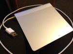
USB Powered Magic Trackpad

Batteries on the Magic Trackpad last an amazingly long time. I would say about 6 months for my usage (on alkaline cells).
Nevertheless, eventually running out of batteries is always annoying so the other day I decided to power the Magic Trackpad using an USB cable.

This mod has already been documented on macrumors.com’s forum. My twist on it was to drill a hole in the stainless steel battery compartment cover instead of leaving wires exposed or drilling through the trackpad’s body.

Be warned that drilling stainless steel requires a lot of patience. You also need a drill that can rotate a slow speed and Cobalt drill bits. It is really important to take your time and not to drill for too long otherwise the heat will turn the stainless steel into super hard steel you will not be able to drill through.
In the case of that battery cover, being small it will get hot very quickly so I drilled for 30 seconds at a time, waiting a minute or two in between to allow for the piece to cool down.
It took me a whole afternoon to drill through the cover!

I used three 1N4001 diodes in series to step the voltage down a bit (from 5V to about 4.2V). You could use an extra two to bring the voltage closer to 3V, but the trackpad doesn’t seem to mind being powered by tensions over 3V (don’t try with more that 5V though) (I’m pretty sure Apple’s engineers used regulators to protect the trackpad’s internals).

In the process, I discovered that the positive end of the battery ersatz have to reproduce the shape of the + side of an AA battery. If the + end is flat it will not work. There is clever mechanism that doesn’t close the electrical circuit to prevent from damaging the trackpad if you insert the AA batteries in the wrong orientation.

Ingredients:

  • A small piece of soft wood, cut down to the dimension of two AA batteries in series
  • Electrical tape
  • A beer cap (for the negative pole)
  • The positive tip of an AA battery
  • A couple of 1N4001 diodes to step down the USB voltage

Bellow are a few pictures of my mod. Enjoy!

Miller 597 – Vintage Rear Dynamo Light / LED modification

Recently, I found a gorgeous looking bicycle rear light on eBay.

It was a bit rusty but after cleaning it the following markings on it became readable:

  • Miller
  • 597

Unfortunately, I couldn’t find much about on Miller as a bicycle light manufacturer and the different models they used to make… If anyone knows about it feel free to leave a reply at the bottom of this post.

597 rear lights are bottle dynamo lights so there is only one piece of wire coming out of the back them, but I converted this one to work of my hub dynamo!

With a  bottle dynamo fitted on your bike, the frame is the return path of the electrical circuit and you only need one piece of wire that runs form the dynamo to the lights to bring the current to the light bulbs.
With dynamo hubs, the frame is not part of the electrical circuit and you need to lay a 2-core wire from the front hub to the lights (usually the front light has a switch that the front and the rear light on & off).

It was quite easy to remove the original one core piece of wire to replace it with a  2-core one: I drilled into the rear of the light through the 1-core wire and also removed all the tar that was used to seal the unit and make the lightbulb holder stay in place.

Next step was looking into how to replace the lightbulb with an LED. LEDs on a bike are advantageous over incandescent lightbulbs because they are absolutely immune to vibrations (there is no filament to break). Incidentally they consume a lot less current but that’s not something you worry much unless you power them out of batteries.

Generators (dynamo) are AC generators. Their output tension is not regulated (the faster you cycle the more energy they produce) so I had to think about voltage and current regulation before using LEDs.

Here is a diagram of the circuit I built and managed to fit inside the 597 (these lights are small!).

The circuit can be broken down in to the following elements

  1. The hub AC generator
  2. The diode bridge that turn AC into DC.
  3. The zener diode that limits the tension to 5.5V
  4. The 0.47F (yes half a Farad) memory backup capacitor that smoothes the DC tension.
  5. The 150mA / 3.3V positive voltage regulator that drop the tension and limits the current in order not to fry the LED
  6. A miniature 1uF capacitor to prevent the regulator from oscillating
  7. A 30 Ohms resistor to lower the tension down a bit before feeding the LED

The design above has the advantage to give a “stand light” facility. That is to say, when you stop cycling (at a red light for instance), the 0.47F capacitor is charged an keeps powering the circuit. Depending on how much current is draw by your LED the light should stay on few minutes after you have stopped.

Design considerations if you if you want more that one LED:

  • Make sure you don’t exceed 150mA of current draw (or use regulators in parallel or a bigger one)
  • Make sure there is always a resistor before each LED if you use LEDs in parallel

List of components:

  • 4 x silicon rectifier diodes (more or less any type will do)
  • 1 x 5W 5.5 Volts Zener Diode
  • 1 x 5.5v 0.47F memory backup capacitor
  • 1 x 3.3V / 150mA positive voltage regulator (TS2950CT or equivalent)
  • 1 x 1 uF electrolytic capacitor
  • 1 x 30 ohms 1/4 watt resistor
  • 1 x red LED

It should cost you less than £10 to source the parts above. If you are based in London, the people at Cricklewood Electronics should have the components needed in stock!

Bellow are two pictures of the modified Miller 597 installed on my road bike.